| Feature | Specs |
|---|---|
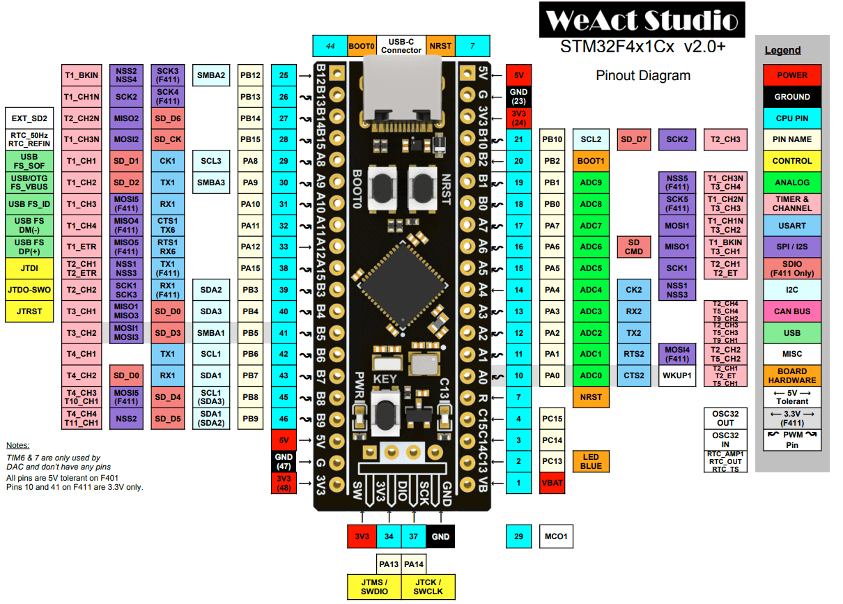
| CPU | Cortex-M4 100MHz |
| RAM | 128kB |
| Flash | 512kB |
| GPIO | 32 |
| ADC | 12 bit |
| USB | 1.1 Host/Device |
| UART | 3 |
| I2C | 3 |
| SPI | 5 |
| I2S | 2 |
| Current consumption | 26mA |
| 32-bit FPU | Use floats instead of doubles |
#include "stm32f4xx_hal.h"
GPIO allows the software to turn on and off a pin and read high or low from a pin.
void HAL_GPIO_WritePin(port, pin, pinState)void HAL_GPIO_TogglePin(port, pin)PinState HAL_GPIO_ReadPin(port, pin)GPIOA, GPIOB, GPIOCGPIO_PIN_1, GPIO_PIN_2, …GPIO_PIN_SET, GPIO_PIN_RESETPWM approzimates an analog voltage by quickly switching between a fixed high voltage and ground so the average over time is the desired analogy voltage.
Microcontrollers use a timer that counts up to a set value, then resets to 0. This is one PWM cycle, consisting of a high phase and a low phase. When the timer count exceeds a compare vlaue, the output switches from high to low. Changing this compare value changes the duty cycle. Chaning the maximum count value changes the resolution. The frequency depends on the clock frequency and the resoltion, where high resoltion lowers the frequency.
Ex: Given a system clock cycle of 72MHz and 8-bit(0-255) resolution, what’s teh frequency of the PWM?
$\frac{72,000,000 \text{ counts}}{1 \text{ sec}} * \frac{1 \text{ cycle}}{256 \text{ counts}} = 218,250 \text{ cycles per second}$
HAL_TIM_PWM_Start(htimPtr, channel);__HAL_TIM_SET_COMPARE(htimPtr, channel, pulse); - Changes the duty cycle.&htim1, &htim2, …TIM_CHANNEL_1, TIM_CHANNEL_2, …HAL_UART_Transmit(uart, bufferArr, size, timeout);HAL_UART_Receive(uart, bufferArr, size, timeout);&huart1, &huart2, etc.sizeof(bufferArr) - 1HAL_I2C_Mem_Write(hi2c, address, regAddress, I2C_MEMADD_SIZE_8BIT, buffer, size, timeout);
HAL_I2C_Mem_Read(hi2c, address, regAddress, I2C_MEMADD_SIZE_8BIT, buffer, size, timeout);
HAL_I2C_Master_Transmit(hi2c, address, buffer, size, timeout);
HAL_I2C_Master_Receive(hi2c, address, buffer, size, timeout);
HAL_I2C_Slave_Transmit(hi2c, buffer, size, timeout);HAL_I2C_Slave_Receive(hi2c, buffer, size, timeout);&hi2c1, &hi2c2, etc. of type I2C_HandleTypeDef0x3C << 1HAL_Delay(uint32_t ms);HAL_GetTick() - Return milliseconds(ms) since startup.HAL_TIM_Base_Start(htim);HAL_TIM_Base_Stop(htim);A watchdog timer - A timer that needs to be periodically refreshed within a time interval, otherwise it resets the device because it indivates the code is no longer runnign corrently.
HAL
TIM2_IRQHandler - is a special function name that matches the entry in the STM32 interrupt vector table for TIM2.
- So when TIM2 throws an interupt event, this function is automatically called.
HAL_TIM_PWM_Start_IT(htim, Channel);
// In my_main.h
#include "usbd_cdc_if.h"
#include <stdio.h>

// Wrapped in extern c
int _write(int file, char *ptr, int len);

// In my_main.cpp wrapped in extern c
int _write(int file, char *ptr, int len) {
	CDC_Transmit_FS((uint8_t*)ptr, len);
	return len;
}

// Usage example
printf("Hello world!\r\n"); // You need \r
screen /dev/ttyACM0 115200 to see terminal output.%f) in printf.# Create an executable object type
add_executable(${CMAKE_PROJECT_NAME})
set_target_properties(${CMAKE_PROJECT_NAME} PROPERTIES LINK_FLAGS "-u _printf_float")
Direct memory access.
| ST-Link Pin | Board Pin |
|---|---|
| GND | GND |
| 3.3v | 3.3v |
| SWDIO | DIO |
| SWCLK | SCLK |
In my_main.h
#include "stm32f4xx_hal.h"

#ifdef __cplusplus
extern "C" {
#endif

// Example of a variable that's declared in main.c
extern TIM_HandleTypeDef htim2;

void myCode();

#ifdef __cplusplus
}
#endif
In my_main.cpp
#include "my_main.h"

#ifdef __cplusplus
extern "C" {
#endif

void myCode(){
	while(true) {}
}

#ifdef __cplusplus
}
#endif
/* USER CODE BEGIN Includes */
#include "../../My_Code/my_main.h"
/* USER CODE END Includes */

// ...

/* USER CODE BEGIN WHILE */
myCode();
/* USER CODE END WHILE */
file(GLOB MY_CODE_SOURCES My_Code/*.cpp)
target_sources(${CMAKE_PROJECT_NAME} PRIVATE
	# Add user sources here
	${MY_CODE_SOURCES}
)
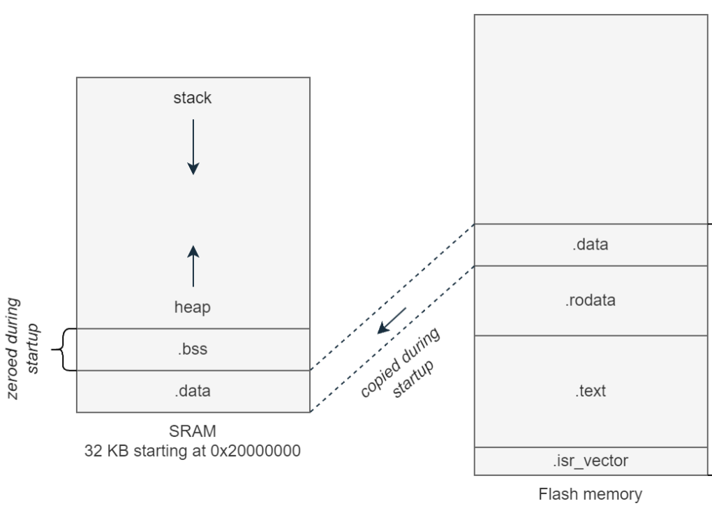
| Memory | Description |
|---|---|
| .isr_vector | Stores interrupt vectors and reset handler addresses. |
| .text | Your code |
| .rodata | Read only constants and literals. |
| .data | Initialized global and static variables. |
| .bss | Uninitialized global and static variables. |