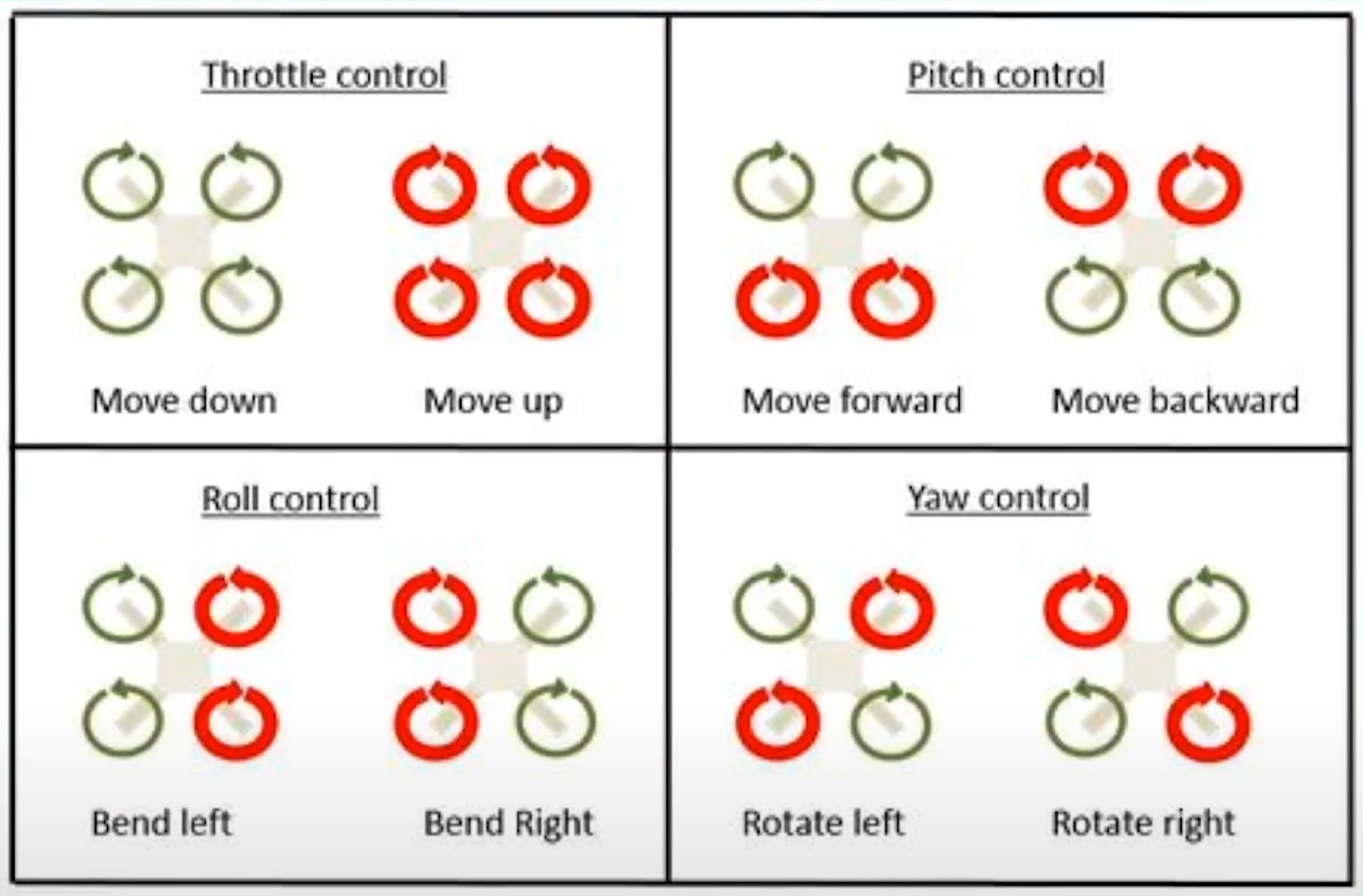
Quadcopters allow you to control all 3 axes with the fewest moving parts.
|
|
There are two important pieces of information you need from the IMU (inertial measurement unit). Rotation rates in degrees per second and angles in degrees. Rotation rates come from the gyroscope. Angles are calculated by fusing data from the gyroscope and accelerometer.
To estimate the drone’s angle from the rate of change on each axis, the data must be integrated over time.
pitch += rate.pitch * deltaTime;The problem with this is that error accumulates, causing the angle estimation to drift over time.
The acceleration from each axis must be converted into an angle.
The problem with this is that it is susceptible to vibrations, so it can’t be used for precise control.
Accelerometer data is usually filtered before calculating angles to reduce vibration noise. A simple approach is averaging a small number of samples (~10). A more advanced method is using a Butterworth filter.
In order to get an accurate drone angle, combine the gyro and acc data to prevent drift and reduce vibrations.
The complementary filter fuses sensor data by weighting each input, usually giving the gyro 90–98% weight.
const double GYRO_WEIGHT = 0.95;
const double ACC_WEIGHT = 0.05;

double combinedPitch = GYRO_WEIGHT * gyroAngle.pitch + ACC_WEIGHT * accAngle.pitch;
| Mode | Description |
|---|---|
| Acro/rate mode | Joystick changes the rate of change of the angle. Just needs gyro data. |
| Angle/stabilized mode | Joystick changes tilt angle and drone auto levels to maintain that angle. |
| Horizon mode | Small stick inputs behave like angle mode and large behave like acro mode. |
The most common stick mode layout mode 2:
| Controller Stick | Direction | Controls |
|---|---|---|
| Left | up/down | Altitude |
| Left | left/right | Yaw |
| Right | up/down | pitch |
| Right | left/right | roll |
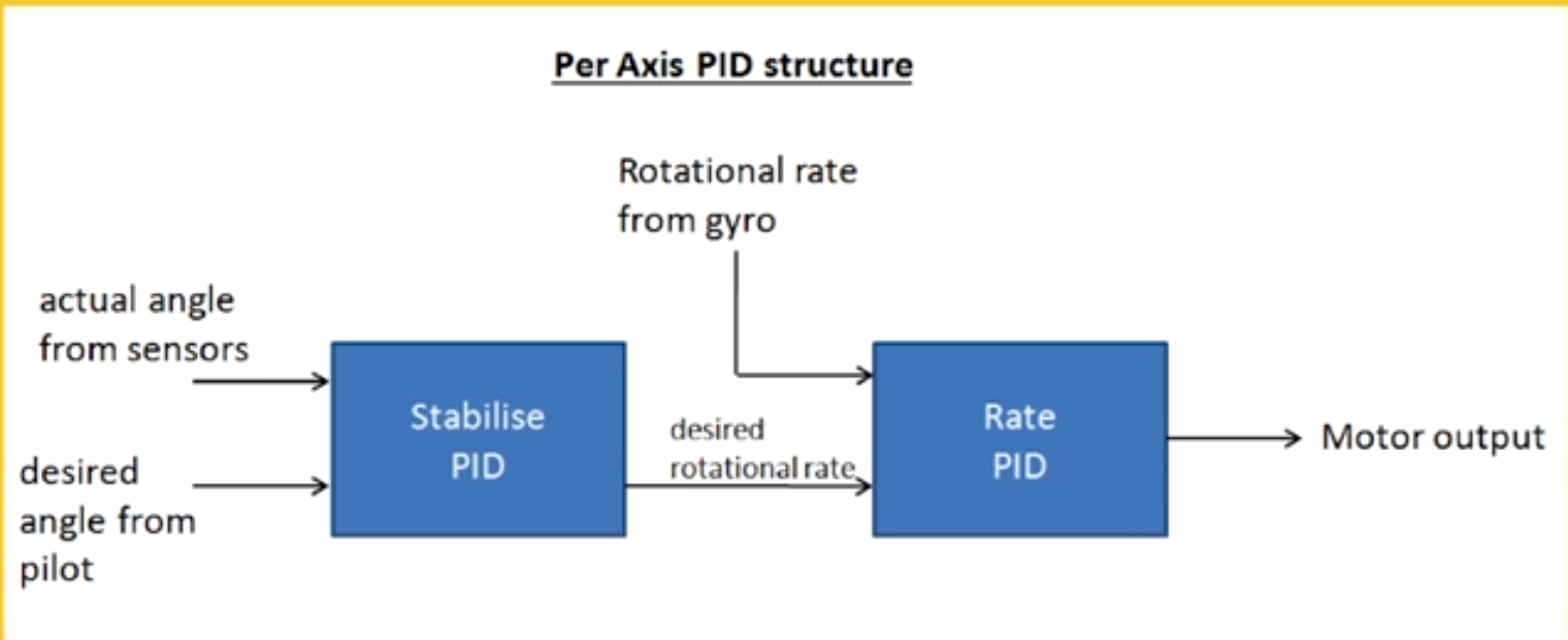
The yaw just uses the rate PID(1st one), while pitch and roll use stabilized PID(2nd one).
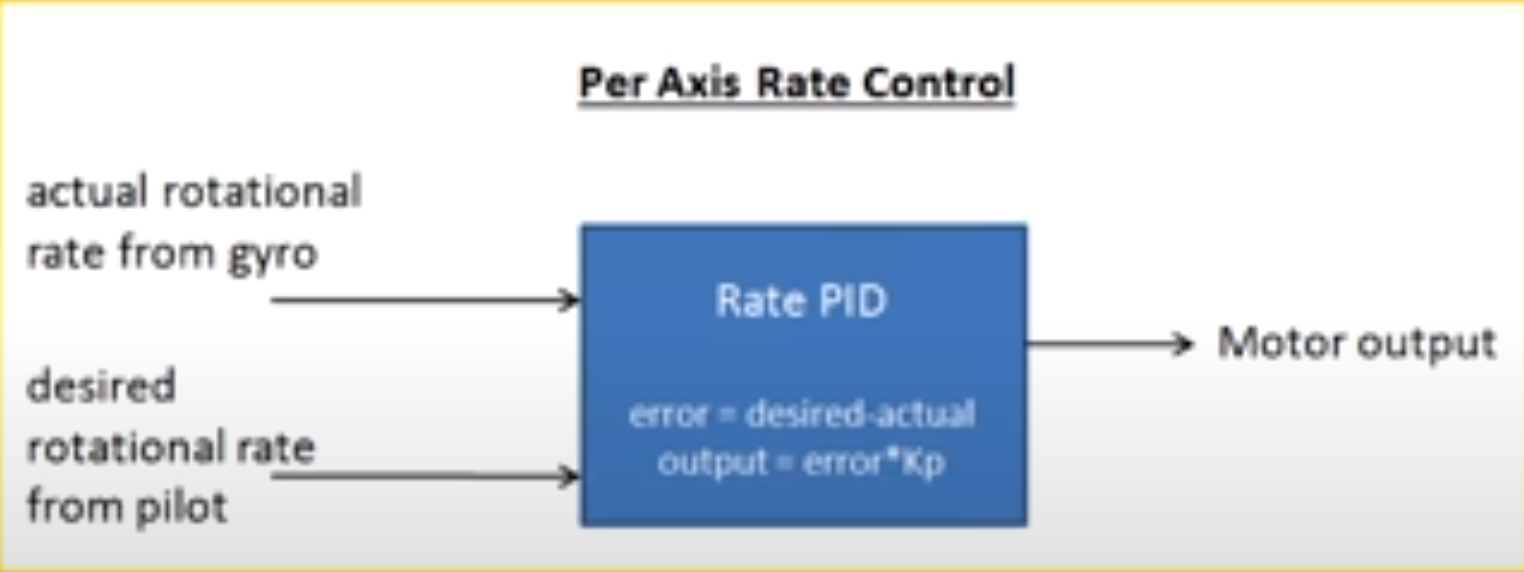
Multiplying the PID output by a constant scales the control signal sent to the motors, effectively tuning how aggressively the drone responds to angle or rate errors.
Each motor combines together the throttle, roll, pitch, and yaw deadening on its position.
Usually ESCs have a range from 1000-2000 PWM.